A breadboard is one of the most useful tools for beginners in electronics. It allows you to build, test, and modify circuits without soldering. Understanding how the holes are internally connected is the key to using a breadboard correctly.
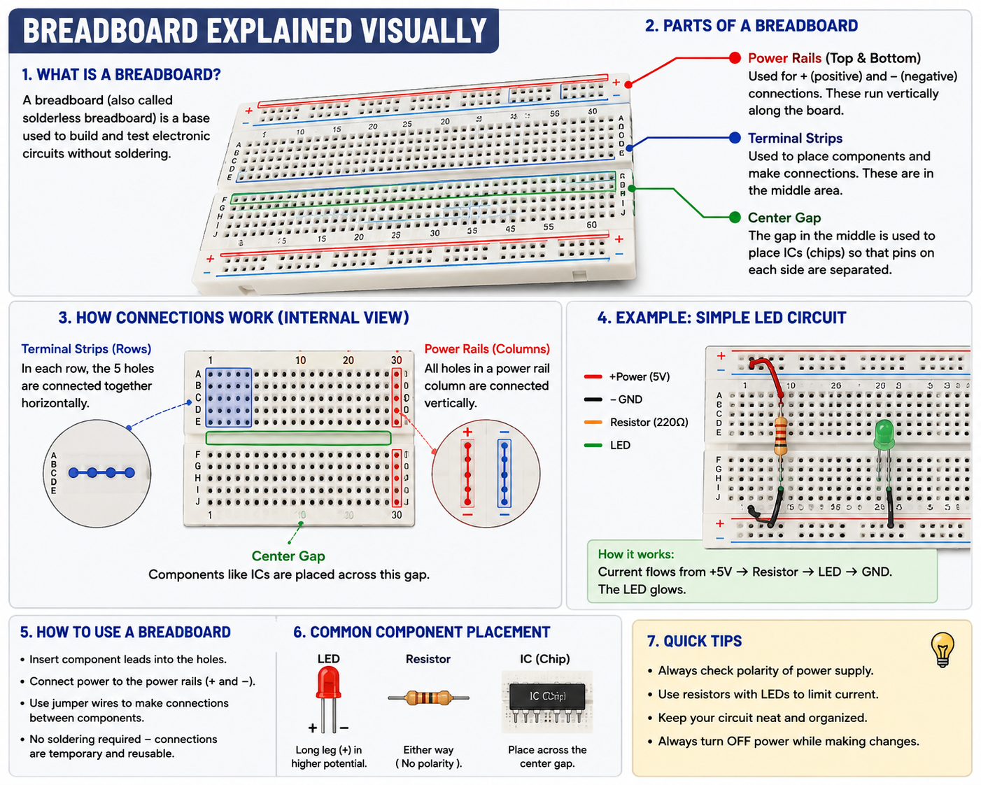
🔌 What Is a Breadboard?
A breadboard, also called a solderless breadboard, is a reusable platform for building temporary electronic circuits.
Instead of soldering components together, you simply insert their leads into the holes and use jumper wires to create connections.
This makes breadboards ideal for:
- Learning electronics
- Arduino projects
- Testing circuit ideas
- Prototyping
- Experimenting with components
🧩 Understanding the Parts of a Breadboard
A typical breadboard has three important areas:
1. Power Rails
The long rows marked + and − are called power rails.
They are commonly used to distribute:
- Positive voltage
- Ground (GND)
For example:
Arduino 5V → + rail
Arduino GND → − rail
You can then connect components to these rails instead of running separate wires back to the Arduino.
2. Terminal Strips
The holes in the central area are where you place components.
The important thing to remember is:
Groups of five holes are internally connected.
For example:
A ●──● B
C ●──● D
D ●──● E
More accurately, a typical group looks like:
A ●
B ●
C ●
D ●
E ●
  │
  └── All five are connected
So if you put one component lead in one of these holes, another wire inserted into the same connected group is electrically connected to it.
🟢 3. The Center Gap
Most breadboards have a gap running down the middle.
The holes on opposite sides of this gap are not connected to each other.
This is particularly useful for placing integrated circuits (ICs).
For example:
A B C D E     F G H I J
● ● ● ● ●     ● ● ● ● ●
● ● ● ● ●     ● ● ● ● ●
● ● ● ● ●     ● ● ● ● ●
        ↑
    Center Gap
An IC can sit across the gap so that its pins remain electrically separated.
🔗 How Breadboard Connections Work
The easiest way to understand a breadboard is to imagine that some holes are secretly connected underneath.
Terminal connections:
● ● ● ● ●
─────────
Connected together
Center gap:
● ● ● ● ●     ● ● ● ● ●
─────────     ─────────
     Separate groups
Power rail:
+  ● ● ● ● ● ● ● ● ●
   │ │ │ │ │ │ │ │ │
   Connected along rail
Note: On some breadboards, power rails may be split in the middle. Always check the particular breadboard rather than assuming an entire rail is continuous.
💡 Building a Simple LED Circuit
Let’s use a basic LED circuit to understand how everything comes together.
Components:
- 5V power source
- Breadboard
- LED
- 220Ω resistor
- Jumper wires
A simplified connection is:
+5V
 │
 │
[220Ω Resistor]
 │
 │
[ LED ]
 │
 │
GND
The resistor limits the current flowing through the LED.
Affiliate links: We may earn a commission if you buy through these links, at no extra cost to you. https://link.amazon/B0azp9Qrd
🔴 LED Polarity Matters
An LED has two terminals:
Anode (+)
Usually the longer lead on a new through-hole LED.
Cathode (−)
Usually the shorter lead and often associated with the flat edge of the LED body.
A basic connection is:
+5V → Resistor → LED → GND
If the LED is reversed, it normally won’t light.
Affiliate links: We may earn a commission if you buy through these links, at no extra cost to you. https://link.amazon/B03B1SsHo
🛠️ How to Build a Circuit on a Breadboard
Step 1: Place the components
Insert the resistor and LED into appropriate holes.
Step 2: Check the connections
Make sure the resistor and LED are actually connected through the breadboard’s internal rows.
Step 3: Connect power
Connect:
5V → positive rail
GND → negative rail
Step 4: Complete the circuit
Use jumper wires to connect the components to the appropriate rails.
Step 5: Power the circuit
Turn on the power and observe the LED.
🔬 Breadboard Example with Arduino
Breadboards are especially useful with Arduino.
A typical beginner project might look like:
Arduino 5V
    │
    ▼
+ Power Rail
    │
    ▼
 Resistor
    │
    ▼
   LED
    │
    ▼
− Ground Rail
    │
    ▼
Arduino GND
For more advanced projects, an Arduino GPIO pin can control the LED instead of connecting it directly to 5V.
This allows software to control the physical circuit.
⚠️ Common Breadboard Mistakes
1. Assuming every hole is connected
They aren’t.
Only specific groups of holes are internally connected.
2. Putting both LED legs in the same connected row
If both LED leads are placed into the same electrical node, the circuit won’t work as intended.
3. Forgetting the resistor
An LED should generally have appropriate current limiting when driven from a voltage source.
4. Connecting power incorrectly
Always check + and GND before powering the circuit.
5. Ignoring split power rails
Some breadboards have breaks in their power rails.
6. Making changes while powered
Turn the power OFF before rearranging connections.
🧠 A Simple Way to Remember Breadboards
Think of a breadboard as a collection of hidden electrical roads.
- Power rails → highways for power
- Terminal strips → small connected groups
- Center gap → separation between the two sides
- Jumper wires → bridges between different areas
Once you understand these hidden connections, breadboards become much easier to use.
🌟 Why Breadboards Are Important for Beginners
Breadboards let you experiment without permanently changing a circuit.
You can:
- Move components
- Change resistor values
- Add sensors
- Connect Arduino boards
- Test different circuit designs
- Quickly fix wiring mistakes
This makes them an essential tool for learning electronics.
🏁 Conclusion
A breadboard provides a simple way to build electronic circuits without soldering. The most important concept is understanding which holes are electrically connected.
Once you understand the power rails, terminal strips, center gap, and internal connections, you can confidently start building LED circuits, Arduino projects, sensor circuits, and many other beginner electronics projects.
At ElectroThink, we believe that understanding how a breadboard works is one of the first steps toward turning electronics theory into practical projects.