 What Is a DC Power Supply?
A DC power supply provides electrical energy where the voltage has a defined polarity and the intended current flows in one direction.
Common DC sources include:
- Batteries
- USB ports
- Power banks
- AC-to-DC adapters
- Bench power supplies
- Solar panels
For example, an adapter might be rated:
5V DC, 2A
This means it provides approximately 5 volts DC and can supply up to 2 amperes, subject to its design and operating conditions.
 Voltage: The First Specification to Check
Voltage is the electrical potential that drives current through a circuit.
Common electronics voltages include:
- 1.5V
- 3.3V
- 5V
- 9V
- 12V
- 24V
The circuit must receive an appropriate voltage.
Example
If a device requires 5V, connecting a 12V supply directly to it can damage it.
So before connecting a power supply, always check the device’s required voltage.
 What Does the Current Rating Mean?
Suppose a power adapter says:
5V — 2A
The 2A rating does not mean that the adapter forces 2A into the circuit.
It means the adapter is capable of supplying up to approximately 2A under its rated conditions.
The load generally draws the current it requires.
Example
A circuit requiring:
5V, 500mA
can normally be powered by a suitable:
5V, 2A
supply.
The extra current capacity is available if the circuit needs it.
 Power Rating
Electrical power can be calculated using: P=V×I
For a 5V, 2A supply: P=5×2=10W
So its nominal maximum output power is approximately 10 watts.

 Polarity
DC supplies generally have a positive and negative terminal.
You may see:
+  → Positive
−  → Negative
For many circuits:
+ → VCC / VIN
− → GND
Polarity is important because reversing it can damage components.
Common Types of DC Power Supplies
1⃣ Battery
A battery is a portable DC source.
Examples:
- AA battery
- 9V battery
- Li-ion battery
- Li-Po battery
Advantages:
- Portable
- No mains connection required
2⃣ USB Power
USB is commonly used for small electronic devices.
Typical systems use:
- 5V USB power
- Higher-voltage USB Power Delivery modes in compatible equipment
Arduino boards and small development boards can often be powered through USB.
3⃣ AC-to-DC Adapter
A wall adapter converts household AC into DC.
For example:
230V AC
   ↓
Adapter
   ↓
5V DC
The adapter handles the conversion and regulation.
4⃣ Bench Power Supply
A bench power supply is particularly useful for electronics experimentation.
Many laboratory supplies allow you to adjust:
- Output voltage
- Current limit
For example:
Voltage: 5.00 V
Current limit: 0.50 A
The current limit provides additional protection during experiments.
 Regulated vs Unregulated Power Supplies
Regulated Supply
A regulated supply attempts to maintain a stable output voltage even when the load changes within its specified operating range.
Example:
5V regulated output
This is generally preferred for sensitive electronic circuits.
Unregulated Supply
An unregulated supply can have an output voltage that changes depending on:
- Load
- Input voltage
- Battery state
- Circuit conditions
Its stated voltage may therefore not be the exact voltage you measure under every condition.
 AC vs DC Power Supply
A simple way to understand the difference:
| Feature | AC | DC |
|---|---|---|
| Direction | Alternates | Unidirectional |
| Common source | Mains | Battery |
| Electronics use | Usually converted | Commonly used directly |
| Example | 230V AC | 5V DC |
Most digital electronics ultimately operate from DC power internally.
Power Supply vs Load
It’s useful to think of an electronic system as having two sides:
[ POWER SUPPLY ] ─────→ [ ELECTRONIC CIRCUIT ]The power supply provides the electrical energy, while the circuit consumes it.
For example:
5V Supply
   │
   ├── Arduino
   │
   ├── Sensor
   │
   └── LED circuit
Each component draws the current it needs, provided the supply is appropriate and the circuit is designed correctly.
 Example: Powering an Arduino Project
Imagine a project containing:
- Arduino
- Temperature sensor
- LED
- Resistor
A suitable supply might provide:
5V DC
The Arduino and other components draw current from the supply.
The important checks are:
- Is the voltage appropriate?
- Is the supply capable of providing the required current?
- Is the polarity correct?
- Are the connections correct?
- Is the power source appropriate for the board?
 What Happens If the Supply Is Undersized?
Suppose your circuit needs more current than the power supply can reliably provide.
You may experience:
- Voltage dropping
- Arduino resetting
- LEDs becoming dim
- Motors failing to start
- Sensors behaving unpredictably
- Power supply overheating or entering protection mode
This is why current capacity matters.
 What Happens If Voltage Is Too High?
Excess voltage can damage components.
For example, if a component is designed for 5V and receives significantly higher voltage, excessive electrical stress can occur.
Always check the component’s specifications before connecting a supply.
 Voltage Regulation
Some circuits require a specific voltage even when the available source is different.
A voltage regulator can help.
For example:
9V DC
  ↓
Voltage Regulator
  ↓
5V DC
  ↓
Circuit
Modern electronics may use linear regulators or switching regulators depending on the application.
 Current Limiting
A current limit can protect a circuit from accidental excessive current.
This is particularly useful with a laboratory bench supply.
For example:
Voltage = 5V
Current Limit = 500mA
If the circuit attempts to draw substantially more than the configured limit, the supply can restrict its output according to its operating mode.
This can help prevent damage during troubleshooting.
 Common Beginner Mistakes
Mistake 1: Looking only at voltage
A supply isn’t suitable simply because its voltage matches.
You should also consider its current capability, polarity, connector, and regulation.
Mistake 2: Reversing polarity
Always identify + and GND before connecting a DC source.
Mistake 3: Using a high-voltage supply
Never assume a device can tolerate a higher voltage just because the connector fits.
Mistake 4: Powering motors directly from GPIO pins
Microcontroller GPIO pins are generally intended for logic-level signals, not for supplying substantial motor current.
Use an appropriate motor driver and suitable external power source.
Mistake 5: Ignoring short circuits
A wiring mistake can cause excessive current. Turn the supply off before changing circuit connections.
 A Simple Rule for Beginners
Before powering any circuit, remember:
V → Voltage
Is the voltage correct?
A → Current
Can the supply provide enough current?
P → Polarity
Are positive and negative connected correctly?
P → Protection
What happens if something goes wrong?
This simple check can prevent many beginner mistakes.
 Conclusion
A DC power supply is the foundation that allows an electronic circuit to operate. Understanding voltage, current capacity, polarity, regulation, power, and protection will help you safely power Arduino projects and other electronic circuits.
Once you understand DC power supplies, you’re ready to move toward more practical topics such as voltage regulators, batteries, Arduino power requirements, and power supply troubleshooting.
At ElectroThink, we believe that understanding where a circuit gets its power is just as important as understanding what the circuit does.
]]> What Is a Short Circuit?
A short circuit happens when two points with different electrical potentials become connected by a path with very low resistance.
Normally, current is supposed to travel through components such as resistors, LEDs, motors, or other loads.
In a short circuit, the current can take a much easier path.
Normal circuit
+ Battery
   │
   ▼
[ Resistor ]
   │
   ▼
[   LED   ]
   │
   ▼
− Battery
Current passes through the intended components.
Short circuit
+ Battery ───────────────┐
                         │
                         │
− Battery ───────────────┘
The positive and negative terminals are connected almost directly.
Because the resistance of the path is very low, a very large current can flow.
Why Does Current Increase?
Ohm’s Law explains the basic principle: I=RV
Where:
- I = Current
- V = Voltage
- R = Resistance
Suppose a 5V supply normally sees a 1kΩ load: I=10005=0.005A
That’s only 5mA.
Now imagine accidentally creating a path with approximately 1Ω: I=15=5A
That’s a huge increase.
In a real circuit, the current won’t necessarily reach exactly this theoretical value because the power supply, wires, PCB traces, and other components have their own resistance and current limits.
What Can Happen During a Short Circuit?
Depending on the power source, a short circuit can cause:
- Excessive current
- Wires or components heating up
- A blown fuse
- Power supply shutdown
- Damaged components
- Burned PCB traces
- Battery overheating
- In serious cases, fire
The amount of danger depends heavily on the voltage, available current, energy capacity, and circuit design.
 Common Causes of Short Circuits
1⃣ Connecting Power and Ground Directly
One of the simplest examples is accidentally connecting:
VCC → GND
For example:
5V ───────── GNDThis creates a very low-resistance path.
2⃣ Incorrect Breadboard Wiring
Breadboards are particularly easy to miswire.
For example, accidentally placing a jumper wire between the positive and negative rails can create:
+ Rail ────────┐
               │
− Rail ────────┘
This can short the power supply.
Always understand the internal connections of your breadboard.
 3⃣ Two Wires Touching
Exposed wires can accidentally touch each other.
For example:
VCC ─────────┐
             │
             │
GND ─────────┘
This can create a short circuit.
Proper insulation and organized wiring reduce this risk.
4⃣ Shorting an LED
Consider this circuit:
5V
 │
[220Ω]
 │
 LED
 │
GND
The resistor limits current.
If a wire accidentally bypasses both the resistor and LED:
5V ───────────── GNDthe current can become dangerously high for the circuit.
5⃣ Shorting a Battery
Batteries can supply significant current.
Connecting the positive and negative terminals directly can cause:
- Rapid heating
- Battery damage
- Leakage
- Venting
- Fire or other hazards, depending on battery chemistry and size
Never intentionally short a battery to demonstrate the concept.
Short Circuit vs Overload
These terms are related but not identical.
Short Circuit
A very low-resistance unintended path causes excessive current.
Overload
A circuit is drawing more current than its intended operating capacity, even though there may not be a direct short.
For example, connecting too many motors to a small power supply can overload it.
How Circuits Protect Against Short Circuits
Electronic systems often include protection mechanisms.
Fuse
A fuse opens the circuit when excessive current flows.
Power → Fuse → CircuitThe fuse sacrifices itself to protect the rest of the system.
Circuit Breaker
A breaker can disconnect power when excessive current is detected and can generally be reset.
Current-Limited Power Supply
Many bench power supplies automatically limit current when a short occurs.
Electronic Protection
Modern circuits may include:
- Over-current protection
- Short-circuit protection
- Thermal protection
- Current limiting
 How to Find a Short Circuit
If your circuit isn’t working, don’t immediately assume the component is faulty.
Step 1: Turn the power OFF
Disconnect the circuit from its power source.
Step 2: Inspect the wiring
Look for:
- Loose wires
- Incorrect jumper connections
- VCC-to-GND connections
- Solder bridges
- Damaged insulation
Step 3: Check the breadboard
Make sure components aren’t accidentally connected through the same internal row.
Step 4: Use a multimeter
With the circuit unpowered, continuity or resistance measurements can help identify an unintended connection.
Be careful: a low resistance reading isn’t automatically a short, because some components naturally have low resistance.
 A Safe Beginner Example
Suppose an Arduino circuit suddenly stops working after connecting a sensor.
Possible causes include:
Arduino 5V ───── Sensor VCC
Arduino GND ──── Sensor GND
If the sensor wiring is accidentally reversed or VCC and GND are connected together, the Arduino’s power supply may shut down or become unstable.
Instead of repeatedly powering the circuit, turn it off and check the wiring systematically.
Short Circuits on Arduino Projects
Arduino projects commonly use:
- Breadboards
- Jumper wires
- Sensors
- LEDs
- Motors
- External power supplies
This creates many opportunities for wiring mistakes.
Before powering an Arduino project, check:
- 5V connections
- GND connections
- Component polarity
- Breadboard rows
- Jumper wires
- External power connections
For motors and other higher-current loads, don’t assume an Arduino GPIO pin can directly power them. Use an appropriate driver circuit and power source.
The Golden Rule
Remember:
Electricity follows available paths. A short circuit gives current an unintended path with very little resistance.
The lower the resistance, the greater the potential current for a given voltage.
Conclusion
Short circuits are among the most common problems beginners encounter while learning electronics. They usually happen because of incorrect wiring, accidental connections between power and ground, damaged insulation, or mistakes on a breadboard.
Understanding Ohm’s Law, circuit paths, breadboard connections, and basic protection will help you prevent and troubleshoot shorts safely.
At ElectroThink, we believe learning not only how circuits work—but also how they fail—is an essential part of becoming confident in electronics.
]]>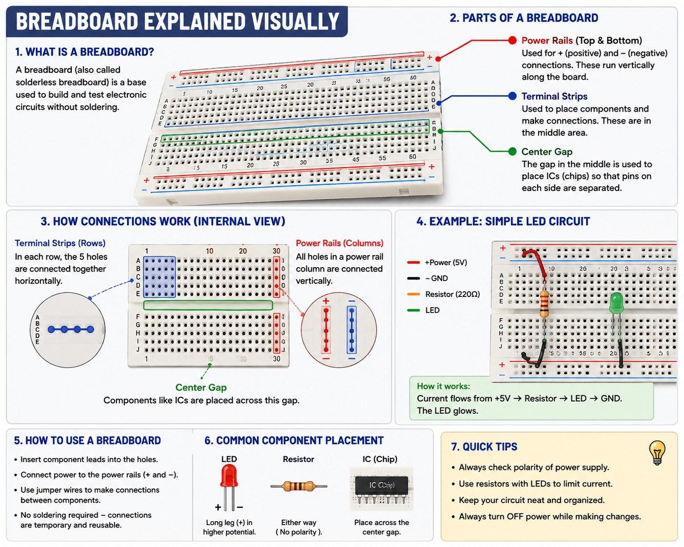
What Is a Breadboard?
A breadboard, also called a solderless breadboard, is a reusable platform for building temporary electronic circuits.
Instead of soldering components together, you simply insert their leads into the holes and use jumper wires to create connections.
This makes breadboards ideal for:
- Learning electronics
- Arduino projects
- Testing circuit ideas
- Prototyping
- Experimenting with components
Understanding the Parts of a Breadboard
A typical breadboard has three important areas:
1. Power Rails
The long rows marked + and − are called power rails.
They are commonly used to distribute:
- Positive voltage
- Ground (GND)
For example:
Arduino 5V → + rail
Arduino GND → − rail
You can then connect components to these rails instead of running separate wires back to the Arduino.
2. Terminal Strips
The holes in the central area are where you place components.
The important thing to remember is:
Groups of five holes are internally connected.
For example:
A ●──● B
C ●──● D
D ●──● E
More accurately, a typical group looks like:
A ●
B ●
C ●
D ●
E ●
  │
  └── All five are connected
So if you put one component lead in one of these holes, another wire inserted into the same connected group is electrically connected to it.
 3. The Center Gap
Most breadboards have a gap running down the middle.
The holes on opposite sides of this gap are not connected to each other.
This is particularly useful for placing integrated circuits (ICs).
For example:
A B C D E     F G H I J
● ● ● ● ●     ● ● ● ● ●
● ● ● ● ●     ● ● ● ● ●
● ● ● ● ●     ● ● ● ● ●
        ↑
    Center Gap
An IC can sit across the gap so that its pins remain electrically separated.
How Breadboard Connections Work
The easiest way to understand a breadboard is to imagine that some holes are secretly connected underneath.
Terminal connections:
● ● ● ● ●
─────────
Connected together
Center gap:
● ● ● ● ●     ● ● ● ● ●
─────────     ─────────
     Separate groups
Power rail:
+  ● ● ● ● ● ● ● ● ●
   │ │ │ │ │ │ │ │ │
   Connected along rail
Note: On some breadboards, power rails may be split in the middle. Always check the particular breadboard rather than assuming an entire rail is continuous.
Building a Simple LED Circuit
Let’s use a basic LED circuit to understand how everything comes together.
Components:
- 5V power source
- Breadboard
- LED
- 220Ω resistor
- Jumper wires
A simplified connection is:
+5V
 │
 │
[220Ω Resistor]
 │
 │
[ LED ]
 │
 │
GND
The resistor limits the current flowing through the LED.
Affiliate links: We may earn a commission if you buy through these links, at no extra cost to you. https://link.amazon/B0azp9Qrd
 LED Polarity Matters
An LED has two terminals:
Anode (+)
Usually the longer lead on a new through-hole LED.
Cathode (−)
Usually the shorter lead and often associated with the flat edge of the LED body.
A basic connection is:
+5V → Resistor → LED → GND
If the LED is reversed, it normally won’t light.
Affiliate links: We may earn a commission if you buy through these links, at no extra cost to you. https://link.amazon/B03B1SsHo
 How to Build a Circuit on a Breadboard
Step 1: Place the components
Insert the resistor and LED into appropriate holes.
Step 2: Check the connections
Make sure the resistor and LED are actually connected through the breadboard’s internal rows.
Step 3: Connect power
Connect:
5V → positive rail
GND → negative rail
Step 4: Complete the circuit
Use jumper wires to connect the components to the appropriate rails.
Step 5: Power the circuit
Turn on the power and observe the LED.
 Breadboard Example with Arduino
Breadboards are especially useful with Arduino.
A typical beginner project might look like:
Arduino 5V
    │
    ▼
+ Power Rail
    │
    ▼
 Resistor
    │
    ▼
   LED
    │
    ▼
− Ground Rail
    │
    ▼
Arduino GND
For more advanced projects, an Arduino GPIO pin can control the LED instead of connecting it directly to 5V.
This allows software to control the physical circuit.
Common Breadboard Mistakes
1. Assuming every hole is connected
They aren’t.
Only specific groups of holes are internally connected.
2. Putting both LED legs in the same connected row
If both LED leads are placed into the same electrical node, the circuit won’t work as intended.
3. Forgetting the resistor
An LED should generally have appropriate current limiting when driven from a voltage source.
4. Connecting power incorrectly
Always check + and GND before powering the circuit.
5. Ignoring split power rails
Some breadboards have breaks in their power rails.
6. Making changes while powered
Turn the power OFF before rearranging connections.
A Simple Way to Remember Breadboards
Think of a breadboard as a collection of hidden electrical roads.
- Power rails → highways for power
- Terminal strips → small connected groups
- Center gap → separation between the two sides
- Jumper wires → bridges between different areas
Once you understand these hidden connections, breadboards become much easier to use.
 Why Breadboards Are Important for Beginners
Breadboards let you experiment without permanently changing a circuit.
You can:
- Move components
- Change resistor values
- Add sensors
- Connect Arduino boards
- Test different circuit designs
- Quickly fix wiring mistakes
This makes them an essential tool for learning electronics.
Conclusion
A breadboard provides a simple way to build electronic circuits without soldering. The most important concept is understanding which holes are electrically connected.
Once you understand the power rails, terminal strips, center gap, and internal connections, you can confidently start building LED circuits, Arduino projects, sensor circuits, and many other beginner electronics projects.
At ElectroThink, we believe that understanding how a breadboard works is one of the first steps toward turning electronics theory into practical projects.
]]>In this beginner-friendly guide, we’ll briefly explain:
- Series connections
- Parallel connections
- Power supply basics
These concepts form the foundation of practical electronics.
What Is an Electronic Circuit?
An electronic circuit is a complete path through which electric current flows.
A basic circuit usually contains:
- Power source
- Wires/connections
- Components (LEDs, resistors, sensors, etc.)
If the path is broken:
- Current stops flowing
- Circuit stops working
1⃣ Series Connections
In a series circuit, components are connected one after another in a single path.
Example:
Battery → Resistor → LED → Switch
Key Characteristics:
- Same current flows through all components
- Voltage gets divided
- If one component fails, entire circuit stops
Simple Analogy
Think of a single road:
- All cars must follow the same path
- Block the road → everything stops
 Advantages of Series Circuits
- Simple to design
- Easy for beginners
- Fewer wires required
Limitations
- One failure affects entire circuit
- Voltage divides between components
 2⃣ Parallel Connections
In a parallel circuit, components are connected across the same voltage source using separate branches.
Example:
Multiple LEDs connected separately to the battery.
Key Characteristics:
- Same voltage across all branches
- Current divides between paths
- One component failure does NOT stop others
Simple Analogy
Think of multiple roads:
- Cars can travel independently
- Blocking one road doesn’t stop others
Advantages of Parallel Circuits
- Independent operation
- Stable voltage for each component
- Common in real electronics systems
Limitations
- More wiring
- Higher total current consumption
 Series vs Parallel Comparison
| Feature | Series | Parallel |
|---|---|---|
| Current | Same everywhere | Divides |
| Voltage | Divides | Same |
| Failure Effect | Entire circuit stops | Others continue |
| Wiring | Simple | More complex |
Both are important in electronics.
3⃣ Power Supply Basics
Every circuit needs a power source.
A power supply provides:
- Voltage
- Current
Without power, no electronic circuit can operate.
Common Power Sources
Batteries
- Portable
- DC power
- Common in beginner projects
USB Power
- 5V DC
- Used for Arduino and sensors
Adapters/Chargers
- Convert AC to DC
- Provide stable voltage
Voltage vs Current in Power Supplies
Voltage
Electrical pressure supplied to the circuit.
Current
Amount of electrical flow available.
Important:
Devices draw the current they need.
Example:
- Arduino may use only small current
- Motors require larger current
Why Correct Power Supply Matters
Wrong power supply can:
- Damage components
- Overheat circuits
- Cause unstable operation
Always check:
- Voltage rating
- Current capability
- Polarity
Polarity Reminder
DC supplies have:
- Positive (+)
- Negative (–)
Reversing polarity may damage components.
Always verify connections before powering ON.
Simple Example Circuit
Components:
- Battery
- LED
- Resistor
Flow:
- Battery supplies voltage
- Current flows through resistor
- LED lights up safely
This simple circuit demonstrates all the basics together.
Common Beginner Mistakes
- Mixing series and parallel incorrectly
- Using wrong voltage supply
- Forgetting resistor with LED
- Reversing polarity
- Loose breadboard connections
Mistakes help you learn faster.
Why Understanding Simple Circuits Matters
Learning these basics helps you:
- Build Arduino projects correctly
- Troubleshoot wiring problems
- Understand schematics
- Design safer circuits
Every advanced electronic system starts with simple circuits.
Conclusion
Series circuits, parallel circuits, and power supply basics are essential foundations of electronics. Once you understand how current flows and how components connect together, building real projects becomes much easier.
At ElectroThink, we believe mastering simple circuits is the first step toward becoming confident in electronics and embedded systems.
]]>In this post, we’ll briefly explain the most essential beginner concepts:
- Voltage
- Current
- Resistance
- Polarity
- Breadboards
- LEDs and resistors
These are the building blocks of electronics.
1⃣ Voltage – The Electrical Pressure
What Is Voltage?
Voltage is the force that pushes electric charge through a circuit.
Think of it like:
Water pressure inside a pipe.
Higher voltage means stronger push.
Unit:
- Volt (V)
Examples:
- AA battery → 1.5V
- USB port → 5V
- Phone charger → 5V–12V
Without voltage, current cannot flow.
2⃣ Current – The Flow of Electricity
What Is Current?
Current is the flow of electric charge through a wire or circuit.
Think of it like:
Water flowing through a pipe.
Unit:
- Ampere (A)
Small electronics usually use:
- mA (milliamps)
Example:
- LEDs often use around 20mA.
Too much current can damage components.
 3⃣ Resistance – Opposition to Current
What Is Resistance?
Resistance limits or slows the flow of current.
Think of it like:
A narrow pipe restricting water flow.
Unit:
- Ohm (Ω)
Why It Matters:
Without resistance:
- LEDs can burn out
- Circuits may overheat
Resistors are used to control current safely.
4⃣ Polarity – Correct Direction Matters
Some electronic components must be connected in the correct direction.
This is called polarity.
Components with Polarity:
- LEDs
- Batteries
- Capacitors
- Diodes
Example:
An LED has:
- Long leg → Positive (+)
- Short leg → Negative (–)
Wrong polarity may stop the circuit from working or damage components.
5⃣ Breadboards – Building Circuits Without Soldering
A breadboard allows you to:
- Build temporary circuits
- Test ideas easily
- Learn safely
Why Beginners Use Breadboards:
- No soldering needed
- Reusable
- Fast circuit modifications
Breadboards contain internal metal connections underneath the holes.
They are perfect for learning and prototyping.
6⃣ LEDs and Resistors
LEDs (Light Emitting Diodes)
LEDs produce light when current flows through them.
Important points:
- LEDs have polarity
- Require proper current control
Why Resistors Are Used with LEDs
If connected directly to a battery:
- Too much current flows
- LED may burn instantly
A resistor limits current to a safe level.
Example:
- 220Ω resistor with 5V supply
Affiliate links: We may earn a commission if you buy through these links, at no extra cost to you.
How These Concepts Work Together
Simple LED circuit:
- Battery provides voltage
- Current flows through circuit
- Resistor controls current
- LED produces light
- Correct polarity ensures operation
This demonstrates the basics of electronics in one circuit.
Common Beginner Mistakes
- Forgetting resistor with LED
- Wrong polarity connection
- Short circuits on breadboard
- Confusing voltage and current
- Using incorrect power supply
Learning from mistakes is part of electronics.
Why These Basics Matter
Understanding these concepts helps you:
- Build circuits confidently
- Start Arduino projects
- Troubleshoot problems
- Learn advanced electronics faster
Strong fundamentals make everything easier later.
Conclusion
Voltage, current, resistance, polarity, breadboards, LEDs, and resistors are the foundation of beginner electronics. Once you understand these basics, you can confidently move toward Arduino, sensors, robotics, and more advanced projects.
At ElectroThink, we believe mastering the basics is the smartest way to start your electronics journey.
]]>From blinking LEDs to smart robots and IoT systems, Arduino makes electronics practical, interactive, and fun.
In this guide, you’ll learn:
- What Arduino is
- Why beginners love it
- Essential prerequisites
- Basic components required
- How Arduino projects work
- Beginner project ideas
 What Is Arduino?
Arduino is an open-source electronics platform based on:
- Simple hardware (microcontroller board)
- Easy-to-use software (Arduino IDE)
It allows users to:
- Read inputs from sensors
- Process data
- Control outputs like LEDs, motors, displays, and more
In simple words:
Arduino acts like the “brain” of an electronics project.
Why Arduino Is Great for Beginners
Arduino is beginner-friendly because:
- Easy programming language
- Large online community
- Low cost
- Simple hardware setup
- Thousands of tutorials available
You can start building projects within hours—even without prior electronics experience.
What Can Arduino Do?
Arduino can be used for:
- LED control
- Home automation
- Robotics
- Temperature monitoring
- Motion detection
- IoT projects
- Smart devices
- Display systems
It connects software with the physical world.
Basic Prerequisites Before Learning Arduino
You do NOT need advanced engineering knowledge, but understanding these basics helps greatly.
1⃣ Basic Electronics Knowledge
You should know:
- Voltage
- Current
- Resistance
- Polarity
- Breadboards
- LEDs and resistors
Without basic electronics, debugging becomes difficult.
2⃣ Understanding Simple Circuits
You should understand:
- Series connections
- Parallel connections
- Power supply basics
Arduino projects are still electronic circuits.
 3⃣ Basic Computer Skills
You should know how to:
- Install software
- Connect USB devices
- Upload files
- Use simple coding tools
No advanced programming needed initially.
 4⃣ Basic Programming Logic
Arduino uses simplified C/C++ style code.
You should understand:
- Variables
- Conditions (if/else)
- Loops
- Functions
Even beginners can learn this gradually.
Get the starter kit via affiiate link https://link.amazon/B0ejrBHBz here.
Essential Components for Beginners
 Arduino Board
Most common:
- Arduino Uno
Best beginner choice because:
- Easy to use
- Well documented
- Widely supported
USB Cable
Used for:
- Power
- Uploading code
Breadboard
Allows building circuits without soldering.
Jumper Wires
Connect components together.
LEDs & Resistors
Used in almost every beginner project.
Sensors (Optional)
Examples:
- Temperature sensor
- Ultrasonic sensor
- Light sensor
Sensors allow Arduino to “sense” the environment.
Understanding How Arduino Projects Work
Every Arduino project follows this basic flow:
INPUT → PROCESS → OUTPUT
Example:
- Button pressed (Input)
- Arduino reads signal (Process)
- LED turns ON (Output)
This is the foundation of embedded systems.
 Arduino IDE (Software)
Arduino IDE is used to:
- Write code
- Compile programs
- Upload to board
Basic structure:
void setup() {
}

void loop() {
}
setup()
Runs once during startup.
loop()
Runs repeatedly forever.
First Beginner Project: Blinking LED
This is the “Hello World” of Arduino.
What It Teaches:
- Digital output
- Timing
- Basic coding
- Uploading programs
Simple but very important.
 Important Concepts to Learn Early
Digital Pins
Used for ON/OFF signals.
Analog Pins
Read varying sensor values.
PWM
Simulates analog output using digital pins.
Serial Monitor
Displays data from Arduino to computer.
Very useful for debugging.
Common Beginner Mistakes
- Wrong wiring
- Missing resistor for LEDs
- Uploading code to wrong board
- Loose breadboard connections
- Using external power incorrectly
Mistakes are part of learning.
Best Beginner Arduino Projects
Start with:
- Blinking LED
- Traffic light system
- Temperature monitor
- Ultrasonic distance sensor
- Automatic night lamp
- Servo motor control
- LCD display project
Build gradually from simple to advanced.
 Why Arduino Is Important
Arduino helps you learn:
- Electronics
- Embedded systems
- Sensors
- Programming
- Automation
- Robotics
- IoT concepts
It is one of the best gateways into modern technology.
Conclusion
Arduino is an excellent platform for beginners to learn electronics and programming together. With basic knowledge of circuits, simple coding, and hands-on practice, anyone can start building exciting real-world projects.
At ElectroThink, we believe Arduino is one of the best tools for turning electronics theory into practical innovation.
]]>In this guide, you’ll learn what the parts are, how to measure voltage, current, resistance, continuity, and diodes, step by step.
 1⃣ Parts of a Digital Multimeter
Before using it, understand the main parts:
Display
Shows measurement value.
Dial (Rotary Selector)
Used to select measurement type:
- V (Voltage)
- A (Current)
- Ω (Resistance)
 (Continuity)
- ➤|— (Diode)
Probe Ports
Usually three or four:
- COM → Black probe
- VΩmA → Red probe (voltage, resistance, small current)
- 10A → Red probe (high current)
Always plug:
- Black → COM
- Red → Correct measurement port
2⃣ Measuring DC Voltage (Most Common Use)
Example: Testing a 9V battery
Step-by-Step:
- Insert probes:
- Black → COM
- Red → VΩ port
- Turn dial to DC Voltage (V⎓)
- Select proper range (if manual)
- Touch:
- Red probe → Positive terminal
- Black probe → Negative terminal
- Read display
Expected:
- A fresh 9V battery → around 8.5–9.5V
If reading is negative, probes are reversed (safe, just swap).
3⃣ Measuring AC Voltage
Example: Checking AC wall outlet ( Be very careful)
Steps:
- Black → COM
- Red → VΩ port
- Turn dial to AC Voltage (V~)
- Carefully insert probes into socket
Expected in India:
- Around 230V
Never touch probe metal parts.
Beginners should avoid mains until confident.
4⃣ Measuring Resistance (Ω)
IMPORTANT: Circuit must be powered OFF.
Example: Checking a 1kΩ resistor
Steps:
- Remove resistor from circuit
- Black → COM
- Red → VΩ port
- Turn dial to Ω
- Touch probes to both resistor leads
- Read value
Expected:
- Around 1000Ω (1kΩ)
If reading shows “OL” → Open circuit.
5⃣ Continuity Test (Very Useful)
Used to check:
- Broken wires
- PCB tracks
- Switches
Steps:
- Turn dial to continuity mode ( symbol)
- Touch probes together
- You should hear a beep
- Test the component/wire
If it beeps → Good connection
No beep → Open circuit
Very useful for troubleshooting.
➤|— 6⃣ Diode Test Mode
Used to test:
- Diodes
- LEDs
Steps:
- Set dial to diode mode
- Red probe → Anode
- Black probe → Cathode
Expected:
- Silicon diode → ~0.6–0.7V
- LED → ~1.8–3V
Reverse probes → “OL”
7⃣ Measuring Current (Be Careful!)
Current measurement requires connecting multimeter in series, not parallel.
Example: Measuring LED current
Steps:
- Move red probe to mA or 10A port
- Break the circuit
- Insert multimeter in series
- Turn dial to A (DC)
- Power ON circuit
Never measure current directly across battery terminals.
 Auto-Ranging vs Manual Multimeter
Auto-Ranging:
- Automatically selects range
- Easier for beginners
Manual:
- Must select range manually
- More control
If unsure, start high range then reduce.
Common Beginner Mistakes
- Measuring resistance in powered circuit
- Probes in wrong port
- Trying to measure current like voltage
- Selecting AC instead of DC
- Ignoring range selection
These can blow the internal fuse.
Safety Tips
- Always start with highest range
- Double-check dial before measuring
- Never measure mains carelessly
- Replace multimeter fuse if blown
- Store properly
Safety first, always.
Why Learning Multimeter Use Is Critical
Mastering the multimeter helps you:
- Debug circuits confidently
- Verify power supply
- Test components
- Avoid guesswork
- Think like an engineer
It’s your electronic stethoscope.
Conclusion
A multimeter is the single most powerful tool in beginner electronics. Once you know how to measure voltage, resistance, current, and continuity properly, troubleshooting becomes simple and logical.
At ElectroThink, we believe hands-on measurement builds real understanding.
]]>In this guide, we’ll cover the must-have tools for beginners, what they are used for, and how to choose them wisely without overspending.
1⃣ Digital Multimeter (Most Important Tool)
What It Does:
- Measures voltage (V)
- Measures current (A)
- Measures resistance (Ω)
- Tests continuity
- Checks diodes
Why You Need It:
A multimeter is the backbone of electronics troubleshooting.
Beginner Tip:
- Start with a basic auto-ranging digital multimeter.
- Ensure it has continuity buzzer.
Without a multimeter, debugging becomes very difficult.
2⃣ Breadboard (For Circuit Building Without Soldering)
What It Does:
- Allows you to build temporary circuits
- No soldering required
- Easy to modify connections
Why It’s Important:
Perfect for:
- Testing ideas
- Learning basics
- Prototyping projects
Breadboards are reusable and beginner-friendly.
3⃣ Jumper Wires
Used with breadboards to connect components.
Flexible wires make circuit building neat and fast.
4⃣ Soldering Iron (For Permanent Connections)
What It Does:
- Permanently joins components to PCB
What to Look For:
- 25W–60W iron
- Temperature control (recommended)
- Good quality solder wire
As you progress, soldering becomes essential.
 5⃣ Wire Cutter & Stripper
Used for:
- Cutting wires
- Removing insulation safely
Avoid using scissors—it damages wires and tools.
 6⃣ Basic Component Kit
A beginner kit should include:
- Resistors
- Capacitors
- LEDs
- Diodes
- Transistors
- Push buttons
- Potentiometers
Having components ready encourages experimentation.
7⃣ Power Supply
Options:
- 9V battery
- Battery holder
- Adjustable bench power supply (advanced)
For beginners:
- Start with low-voltage DC (5V–12V)
Safety first—avoid direct mains power.
8⃣ LED Assortment
Great for:
- Learning polarity
- Testing circuits
- Practicing resistor calculations
LEDs provide instant visual feedback.
9⃣ Basic Microcontroller Board (Optional but Recommended)
Examples:
- Arduino-type boards
- ESP modules
They help you:
- Learn digital electronics
- Practice programming + hardware
Excellent for hands-on projects.

 Notebook & Circuit Diagrams
Often ignored but very important:
- Draw circuits
- Write calculations
- Track mistakes
Engineers document everything.
Safety Tools (Highly Recommended)
- Insulated screwdriver
- Safety glasses
- Heat-resistant mat
- Proper ventilation (for soldering)
Never ignore safety.
Affiliate links: We may earn a commission if you buy through these links, at no extra cost to you. https://link.amazon/B03B1SsHo
 Budget-Friendly Starter Setup
If you’re starting with limited budget:
Must-have:
- Multimeter
- Breadboard
- Jumper wires
- Resistors + LEDs
- 5V or 9V supply
You can build many learning circuits with just these.
Common Beginner Mistakes
- Buying expensive tools too early
- Working directly with AC mains
- Not checking polarity
- Skipping multimeter use
- Poor soldering habits
Start simple. Upgrade gradually.
Why Tools Matter in Electronics
Good tools:
- Improve accuracy
- Reduce frustration
- Save time
- Make learning fun
Electronics is practical—tools are your learning partners.
Conclusion
Starting electronics doesn’t require expensive equipment. With a few essential tools and curiosity, you can build, test, and understand real circuits.
At ElectroThink, we believe the right tools combined with strong fundamentals create confident electronics learners.
]]>In this article, we’ll explore what’s inside a power adapter, how it works step by step, and why it’s safe, explained in simple terms.
What Is a Power Adapter?
A power adapter is a device that:
- Converts AC mains power into low-voltage DC
- Supplies the correct voltage and current
- Protects the device from electrical damage
Example:
- Wall supply → 230V AC
- Phone needs → 5V DC
The adapter makes this conversion safely.
Why Power Adapters Are Needed
Household electricity:
- High voltage (230V AC)
- Dangerous for electronics
Electronic devices:
- Low voltage DC
- Stable and precise power required
Power adapters act as a bridge between the grid and electronics.
Two Main Types of Power Adapters
1⃣ Linear Power Adapters (Older Type)
- Use transformer + rectifier
- Heavy and bulky
- Less efficient
2⃣ SMPS (Switch Mode Power Supply) – Modern Type
- Lightweight
- Highly efficient
- Used in phone and laptop chargers
Most modern adapters are SMPS-based.
Inside a Typical SMPS Power Adapter
Let’s break it down step by step.
1. Input Protection Stage
Components:
- Fuse
- MOV (surge protector)
- EMI filter
Purpose:
- Protects against voltage spikes
- Reduces electrical noise
- Prevents fire hazards
Safety always comes first.
2. Rectifier Stage
Components:
- Bridge rectifier (diodes)
What it does:
- Converts AC to pulsating DC
This is the same rectifier principle you learned earlier.
3. High-Voltage DC Filtering
Components:
- Large electrolytic capacitor
Purpose:
- Smooths pulsating DC
- Stores energy briefly
At this stage, voltage is still high (≈325V DC).
4. Switching Stage (Heart of SMPS)
Components:
- Switching transistor (MOSFET)
- PWM controller IC
What happens:
- DC is rapidly switched ON and OFF
- Switching happens at high frequency (kHz)
This allows efficient voltage reduction.
5. High-Frequency Transformer
Purpose:
- Steps down voltage
- Provides electrical isolation
High frequency → small transformer → compact charger
This is why modern adapters are lightweight.
6. Secondary Rectification
Components:
- Fast diodes or Schottky diodes
Purpose:
- Converts high-frequency AC back to DC
7. Output Filtering & Regulation
Components:
- Capacitors
- Inductors
- Feedback circuit
Purpose:
- Smooth DC output
- Maintain stable voltage under load changes
Ensures your phone gets clean, stable power.
 Feedback & Voltage Regulation
A feedback circuit:
- Monitors output voltage
- Adjusts switching duty cycle
- Keeps voltage constant
This is why:
- Phone charges safely
- Overcharging is avoided
Power Ratings Explained
Example: 5V, 2A charger
- Voltage → 5V
- Maximum current → 2A
- Power → 10W
Charger supplies only what device demands, not more.
Safety Features Inside Adapters
Modern adapters include:
- Over-voltage protection
- Over-current protection
- Short-circuit protection
- Thermal shutdown
- Electrical isolation
Cheap adapters often skip these—making them dangerous.
Common Myths
Higher-amp charger damages phone Phone draws only required current
All chargers are same Quality and safety vary greatly
Adapters waste lot of power SMPS efficiency is very high
Why Understanding Power Adapters Matters
Knowing how adapters work helps you:
- Choose safe chargers
- Avoid cheap, unsafe products
- Understand SMPS basics
- Learn power electronics
It also explains why original chargers matter.
Conclusion
Power adapters are compact power conversion systems that safely transform dangerous high-voltage AC into usable low-voltage DC. Inside them lies a smart combination of rectifiers, switching circuits, transformers, and regulators.
At ElectroThink, we believe understanding what’s inside everyday electronics builds true engineering intuition.
]]>In this post, we’ll explain what an AC waveform is, its shape, key terms, and why it matters, in simple language.
 What Is an AC Waveform?
An AC waveform is a graphical representation of how voltage or current changes with time.
In AC:
- Voltage rises from zero to a positive peak
- Falls back to zero
- Reverses direction to a negative peak
- Repeats this cycle continuously
This repeating pattern is called a cycle.
The Sine Wave (Most Common AC Waveform)
The most common AC waveform is the sine wave.
Why Sine Wave?
- Smooth and continuous
- Easy to generate using rotating generators
- Causes less energy loss
- Ideal for power transmission
Mains electricity is a sine wave.
 Key Parts of an AC Waveform
1⃣ Cycle
One complete positive and negative swing of the waveform.
2⃣ Amplitude (Peak Value)
- Maximum value of voltage or current
- Measured from zero to peak
Higher amplitude means higher voltage.
3⃣ Peak-to-Peak Value
- Total height from negative peak to positive peak
- Equal to 2 × peak value
4⃣ Time Period (T)
- Time taken for one complete cycle
- Measured in seconds
5⃣ Frequency (f)
- Number of cycles per second
- Measured in Hertz (Hz)
f=T1
Example:
- 50Hz → 50 cycles per second
AC Voltage Values Explained
Peak Voltage (Vp)
Maximum voltage of the waveform.
RMS Voltage (Vrms)
Root Mean Square value represents the effective DC value.Vrms=2Vp
Example:
- 230V AC (India) → 325V peak
RMS value does the real work.
Average Value
- Average over a full cycle is zero
- Used mainly in rectifier analysis
Phase in AC Waveforms
Phase describes the position of one waveform relative to another.
- In-phase → rise and fall together
- Out-of-phase → shifted in time
Phase difference is measured in degrees (°).
AC Waveform in Real Systems
- Household supply → sine wave
- Inverters → sine or modified sine
- SMPS → chopped waveforms
- Audio signals → complex AC waves
Not all AC waves are perfect sine waves.
Why AC Waveform Matters
Understanding AC waveforms helps you:
- Analyze power systems
- Design filters
- Understand transformers
- Work with AC circuits safely
Waveform shape affects performance and efficiency.
Simple Visualization Example
Imagine a rotating generator:
- Coil rotates in magnetic field
- Induced voltage changes smoothly
- Produces sine wave output
This is the origin of AC.
Common Beginner Mistakes
- Confusing peak with RMS value
- Ignoring frequency
- Assuming AC voltage is constant
- Forgetting phase difference
- Misreading waveform graphs
Understanding the basics prevents errors.
Conclusion
An AC waveform shows how voltage or current changes with time. The sine wave, frequency, amplitude, RMS value, and phase are key concepts that explain how AC power works in real life.
At ElectroThink, we believe mastering AC waveform basics builds a strong foundation for learning power and electrical engineering.
]]>